




-
 Media gallery
-
 Media gallery
-
 Media gallery
-
 Media gallery
-
 Media gallery
-
 Media gallery
-
 Media gallery
-
 Media gallery
-
 Media gallery
-
 Media gallery
-
 Media gallery


Adjustable Voltage Regulator Module DC-DC Power Supply 3.3V/5V Fixed & 1.2V-24V Adjustable Output, MP2491C with Digital Display & Protection for Raspberry Pi / Robot / Embedded Projects
- Regular price
- $19.00
- Regular price
-
- Sale price
- $19.00
- Unit price
- per
Couldn't load pickup availability


Have a question?
Notified by email when this product becomes available
- Description
- Manual
- Shipping Policy
- Reviews
Overview
The Adjustable Buck Voltage Regulator Module is a high-efficiency 3-channel synchronous buck power module built with 3 genuine MPS MP2491C chips. From a single 6V–24V DC input, it delivers three independent voltage rails—a 1.2V–24V adjustable output plus fixed 5V and fixed 3.3V—ideal for powering Raspberry Pi, MCUs, servos, motors and sensors from one compact board.
Equipped with a real-time digital voltmeter, a master power switch and full-circuit protection, it solves the pain points of messy multi-power wiring, unstable voltage and easy burnout in robot car and embedded development scenarios.
Note: This is a step-down (buck) only module. The input voltage must be at least output voltage + 0.5V; it cannot boost voltage.
Key Features
⚡ 3 Independent High-Power Output Channels
- One Adjustable + Two Fixed Rails: 1.2–24V adjustable output plus fixed 5V and fixed 3.3V; each channel is independently regulated (common ground, shared input).
- High Current Output: Up to 5A on a single channel; up to 4.5A per channel when all 3 channels are loaded simultaneously.
🔹 Genuine MP2491C High-Performance Chips
- Up to 95% Efficiency: Synchronous rectification architecture for cool, efficient operation.
- Ultra-Fast Transient Response: COT control keeps the voltage drop to only ~200mV under a 0-to-5A load step.
- Low Ripple: 52mV typical (peak-to-peak) on the 5V output—stable power for sensitive electronics.
📊 Built-in Digital Voltmeter
- Real-Time Monitoring: Onboard 3-digit digital voltmeter with a reading accuracy of ±1%.
🔌 Flexible Input Options & Master Switch
- 3 Input Methods: KF301-2P screw terminal, XH2.54-2P socket, or DC 5.5×2.5mm barrel jack—use only ONE input source at a time.
- Master ON/OFF Slide Switch: Convenient power control right on the board.
🛡️ Full-Circuit Safety Protection
- Input Reverse-Polarity Protection: The red power LED stays off when the input is reversed.
- Output Protection: Over-current hiccup protection, over-voltage protection and short-circuit protection (the blue channel LED turns off as the alert).
- Over-Temperature Protection: Thermal shutdown protects the board under sustained load.
🧩 Practical Design for DIY
- Better Heat Dissipation: Large-area copper thermal pad on the bottom of the PCB.
- Standard M2.5 Mounting Holes: Compatible with most chassis and device stacks.
- Out-of-Box Use: Mounting hardware and a tuning screwdriver are included.
Power Requirements & Safety Guide
⚠️ IMPORTANT — READ BEFORE POWERING ON:
- Buck Only: The input voltage must be higher than the set output voltage (a differential of at least 0.5V is recommended). For example, for a stable 12V output, the input should be between 12.5V and 24V.
- Never Reverse the Ports: Never connect the input power source to the output terminals. The input voltage must not exceed 24V.
- One Input Source at a Time: Do not connect multiple power sources to different input interfaces simultaneously.
- Multi-Channel Derating: When operating all 3 channels at full load, the current limit is 4.5A per channel.
- Placement & Mounting: Place the module on a non-conductive surface; tighten all mounting screws securely to prevent short circuits.
- Ventilation: For continuous high-current operation, ensure adequate ventilation and do not obstruct the heat dissipation area on the underside.
Note: Issues resulting from improper operation or misuse are not covered under the product warranty.
Technical Specifications
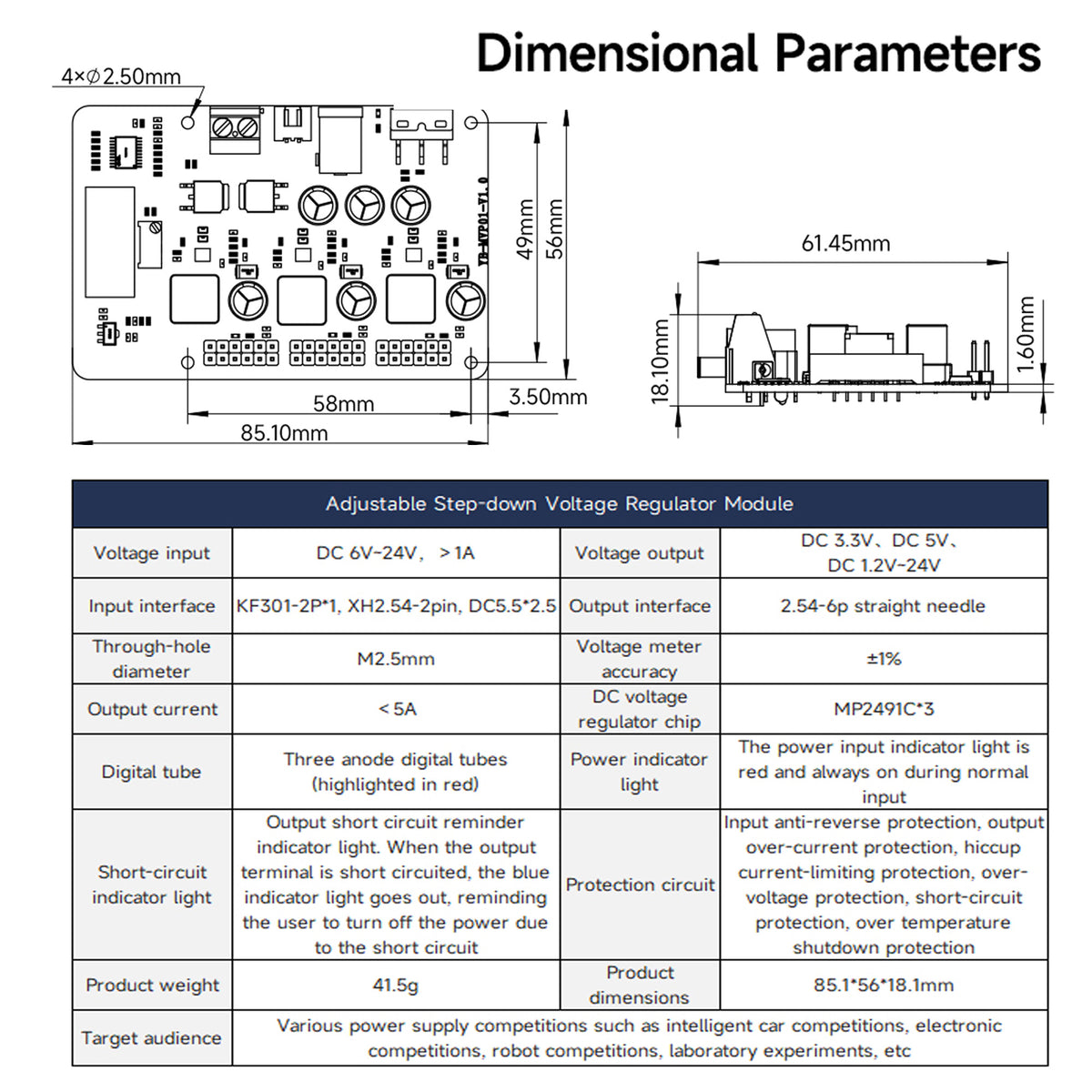
| Feature | Specification |
|---|---|
| Voltage Input | DC 6V–24V; the input power supply must support sufficient current for the total load |
| Voltage Output | DC 3.3V, DC 5V, DC 1.2V–24V (adjustable) |
| Output Current | Single channel: max 5A 3 channels simultaneous load: max 4.5A per channel |
| Regulator Chip | 3 × MP2491C (synchronous buck) |
| Input Interface | KF301-2P screw terminal, XH2.54-2Pin socket, DC 5.5×2.5mm barrel jack |
| Output Interface | 2.54-6P straight pin header |
| Digital Voltmeter | 3-digit red LED display (monitors the adjustable rail only), ±1% accuracy |
| Power Indicator | Red LED, always on during normal input |
| Short-Circuit Indicator | Blue LED turns off when the output is short-circuited, reminding the user to turn off the power |
| Protection Circuit | Input anti-reverse protection, output over-current protection, hiccup current-limiting protection, over-voltage protection, short-circuit protection, over-temperature shutdown protection |
| Mounting Hole Diameter | M2.5mm |
| Dimensions | 85.1 × 56 × 18.1 mm |
| Net Weight | 41.5 g |
| Target Applications | Intelligent car competitions, electronics and robotics competitions, laboratory experiments and other power supply scenarios |
Packing List
- 1 x Adjustable Buck Voltage Regulator Module (YB-MVP01)
- 4 x M2.5 Brass Standoffs
- 4 x Screws & 4 x Matching Nuts
- 1 x Mini Screwdriver (for voltage adjustment)
- 1 x XH2.54 Ribbon Cable (15cm)
- Note: Raspberry Pi / single board computer, motors, servos, sensors, battery, DC power adapter and T-Plug cable are not included.
Refer to: https://wiki.geekworm.com/YB-MVP01
Please email to us at info@geekworm.com if you have other questions.
We send orders to worldwide with tracking number.
For detail refer to Shipping Policy