




-
 Media gallery
-
 Media gallery
-
 Media gallery
-
 Media gallery
-
 Media gallery


LM2596 3-Output DC-DC Buck Converter Module — 3.3V, 5V & Adjustable
- Regular price
- $15.00
- Regular price
-
- Sale price
- $15.00
- Unit price
- per
Couldn't load pickup availability


Have a question?
Notified by email when this product becomes available
- Description
- Manual
- Shipping Policy
- Reviews
Overview
This compact DC-DC step-down power module provides three voltage rails: 3.3V, 5V, and an adjustable output. It is designed for electronic prototyping, sensor power distribution, and DIY projects that require multiple DC supply voltages. The 60 × 40 mm PCB includes a DC barrel input, a screw terminal input, an onboard power switch, and output indicator LEDs.
Each rail provides five output/GND connection positions for convenient wiring to multiple loads at the same voltage. These are three voltage rails, not fifteen independently regulated outputs.
This description covers the black PCB version with output headers not soldered. Images with installed headers illustrate the assembled connection layout.
Features
- Three output rails: fixed 3.3V, fixed 5V, and one potentiometer-adjustable output.
- Two input options: a DC barrel jack or a two-position screw terminal. Use only one input at a time.
- Onboard power switch: slide left to turn on, using the front-view orientation shown in the pinout diagram.
- Output status LEDs: PWR1, PWR2, and PWR3 correspond to the 3.3V, 5V, and adjustable rails.
- Five connection pairs per rail: each output group has a 2 × 5 layout, with voltage outputs in the top row and GND in the bottom row.
- Compact mounting: 60 × 40 mm PCB with four corner mounting holes.
Specifications
| Item | Specification |
|---|---|
| Module type | DC-DC step-down / buck converter |
| Product series designation | LM2596 |
| Brand marking on PCB | RYDZ |
| Version | Black PCB; output headers not soldered |
| Output rails | 3.3V, 5V, and adjustable |
| Maximum input voltage | 35V DC, as marked by the supplier on the PCB |
| Recommended input for fixed outputs | 7–35V DC when using only 3.3V/5V; application recommendation, not tested over the full range |
| Input for adjustable output | Above the target output with sufficient headroom; 35V maximum; approximately 15V input recommended for 13.5V output |
| Minimum input voltage | Not specified by the supplier or established in this test |
| Adjustable output ceiling | 13.5V, as marked by the supplier; achievable output depends on input voltage and load conditions |
| Output current marking | Supplier-stated maximum of 3A per rail; this is not a continuous-load rating for one rail or all three rails simultaneously |
| Input connectors | DC005 barrel jack and KF301-2P screw terminal (5 mm pitch); use one only |
| Output connections | Three 2 × 5 groups, with five voltage/GND connection pairs per rail |
| Voltage adjustment | Onboard potentiometer for the adjustable rail |
| Power control | Onboard slide switch |
| Indicators | PWR1, PWR2, and PWR3 |
| PCB dimensions | 60 × 40 mm |
| Mounting-hole center spacing | 54 × 33.9 mm, according to the supplier's drawing |
Usable load current depends on input/output voltage, cooling, wiring, and ambient temperature. The five connection pairs on each rail share that rail's current capacity; they are not individually rated for 3A. Do not connect different voltage outputs together.
Choosing the Input Supply
For the fixed 3.3V and/or 5V outputs only, the recommended input is 7–35V DC. This is an application recommendation. The supplier has not specified the module's minimum input voltage, and the full input range has not been tested in this evaluation.
When using the adjustable output, select the input according to the target output voltage. The input must be higher than the target output, with sufficient voltage headroom for step-down regulation, and must not exceed 35V. Do not treat 12–35V as a universal operating range or assume that an arbitrarily small voltage difference is sufficient. If the fixed outputs are also used, their input requirements must also be met.
For example, an input of approximately 15V DC is recommended for a 13.5V output. The tested sample produced approximately 13.55V without an external load while the supply displayed 15.00V. Required headroom, voltage stability, and temperature rise under load have not been verified and should be checked in the intended application. A 12V input cannot be boosted to 13.5V by this module.
35V is the supplier's maximum input limit. Allow for supply tolerance and voltage fluctuations so that the actual input does not exceed this limit.
No-Load Test Results
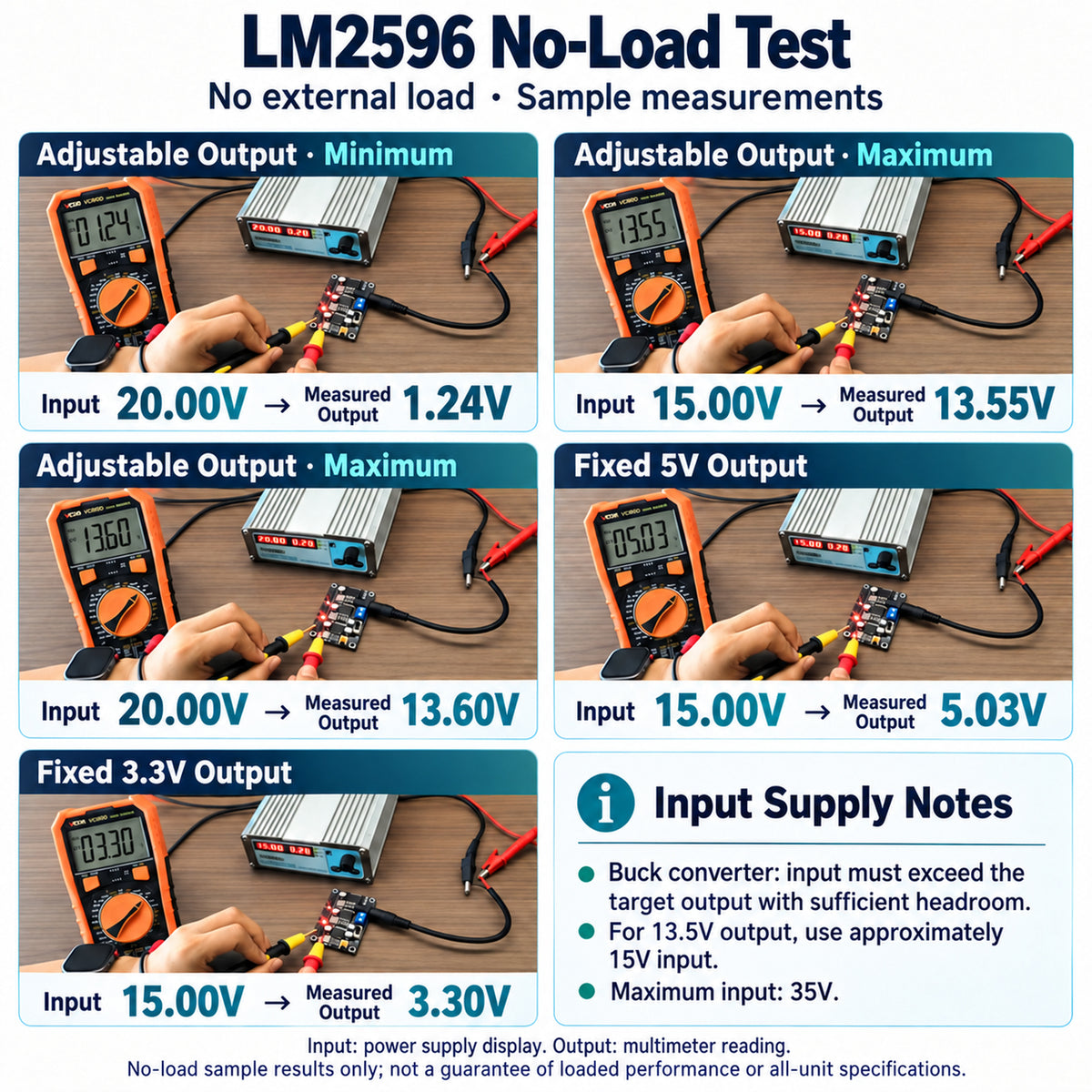
The following readings are from sample test photographs with no external load connected. Input values are the power supply's displayed readings, not separate measurements at the module's input terminals.
| Test | Supply display | Multimeter output reading |
|---|---|---|
| Adjustable output, trimmer at minimum | 20.00V | 1.24V |
| Adjustable output, trimmer at maximum | 15.00V | 13.55V |
| Adjustable output, trimmer at maximum | 20.00V | 13.60V |
| Fixed 5V output | 15.00V | 5.03V |
| Fixed 3.3V output | 15.00V | 3.30V |
The supplier specifies a maximum adjustable output of 13.5V. These sample readings are for reference only and do not establish a guaranteed adjustment range, output accuracy, or performance under load for all units. The 13.60V reading does not replace the specified output ceiling, and 1.24V is not a guaranteed adjustment minimum. Continuous current, full-load performance, and simultaneous loading of all three rails have not been tested.
Connections and Pinout
The following positions refer to the component side facing you, with the input connectors at the top and output headers at the bottom.
| Position or marking | Function |
|---|---|
| Power Input 1: blue screw terminal | External DC input; follow the + / − markings on the PCB |
| Power Input 2: black barrel jack | Alternative DC input connection |
| Top slide switch | Module power control; slide left to turn on |
| Orange potentiometer at the upper right | Adjusts the variable output voltage |
| Left output group, top row | 3.3V output |
| Center output group, top row | 5V output |
| Right output group, top row | Adjustable output |
| Bottom row of all three groups | GND |
| PWR1 / PWR2 / PWR3 | 3.3V / 5V / adjustable-output indicators |
The top row is nearer the components; the bottom row is nearer the board edge. Left and right are reversed when viewing the back of the board. Always check the PCB markings.
Getting Started
- With power disconnected, check the required input and load voltages, polarity, and connection positions.
- Connect a DC supply to one input connector only. Do not use both inputs simultaneously.
- Leave the load disconnected and turn on the module. For the adjustable rail, measure between its output and GND with a multimeter, then adjust the potentiometer gradually to the required voltage.
- Turn power off, connect the load to the appropriate output and GND, then turn power on again.
- Check output voltage and indicator LEDs. Monitor temperature and voltage stability under the actual load. Disconnect power and investigate any abnormal behavior.
Important Notes
- This is a DC step-down module. It cannot boost a lower input voltage. The input must be above the required output with sufficient operating headroom.
- Do not exceed the supplier-marked 35V maximum input. A maximum rating is not a recommended continuous operating point.
- Measure and set the adjustable output before connecting a load.
- Use only one input connector. Follow the polarity markings on the screw terminal.
- Verify plug dimensions and polarity before using a DC barrel power adapter.
- Avoid output shorts and do not parallel different voltage rails. Keep the underside of the PCB away from conductive surfaces.
- Output headers are not soldered on this version. Soldering is required before using pin-header connections.
FAQ
Are the five connection pairs five separate regulated outputs?
No. The five pairs in each voltage group belong to the same rail and share its available load capacity.
Can both input connectors be used at the same time?
No. Choose either the DC barrel jack or the screw terminal input.
Is the adjustable rail a fixed 12V output?
No. Set it with the potentiometer and verify the voltage before connecting a load. The achievable voltage depends on the input supply and operating conditions.
Can it power any development board directly?
Check the device's voltage, current, connector, and power-input requirements first. This module does not provide USB power negotiation, so a matching voltage alone does not establish compatibility.
Please email to us at info@geekworm.com if you have some questions.
We send orders to worldwide with tracking number.
For detail refer to Shipping Policy